
Skalnav across industries — find out how.
The same physics-based shell buckling engine, tuned to the loads, fabrication tolerances, and standards that matter in each sector.
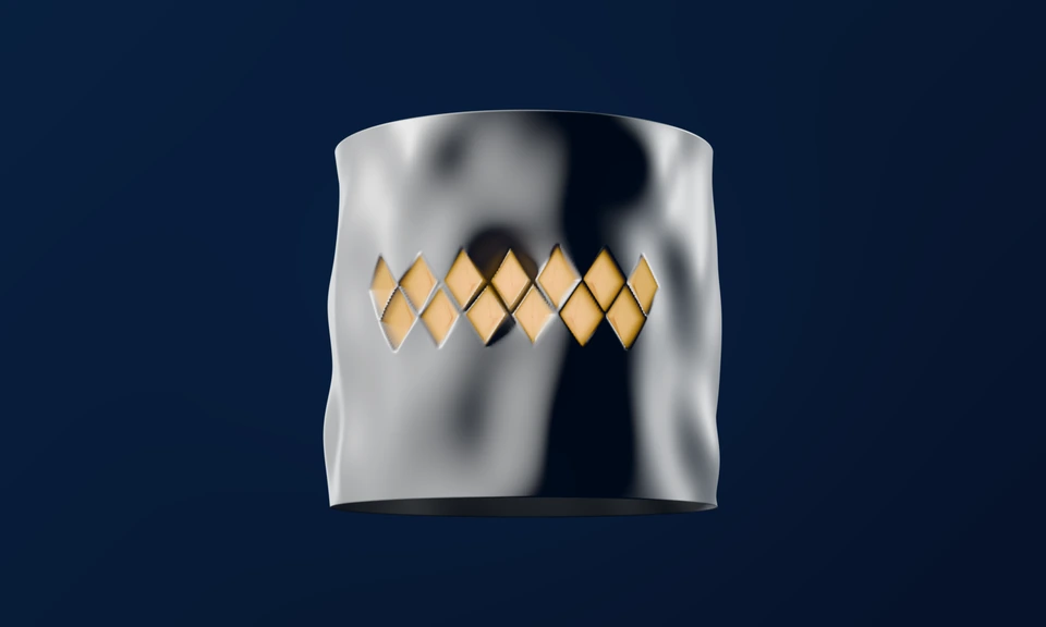
Aerospace
Launcher tank barrels, interstages and domes. Axial compression plus bending, with internal pressure where it acts; domes under external pressure. The knockdown follows the imperfection amplitude you enter, not a fixed empirical design curve. Where buckling sizes the wall, a knockdown for your own shell shows whether it needs a thicker wall or allows a thinner wall; on a launcher, structural mass trades against payload.
Watch the film ↓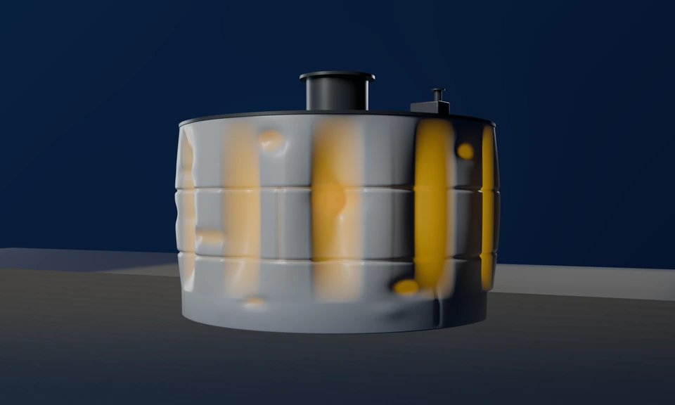
Wind Energy
Onshore tower sections and suction-bucket skirts. Tower walls under self-weight and overturning moment, and the fabrication tolerance class from a measured imperfection field, using the implemented EN 1993-1-6 procedures.
Watch the film ↓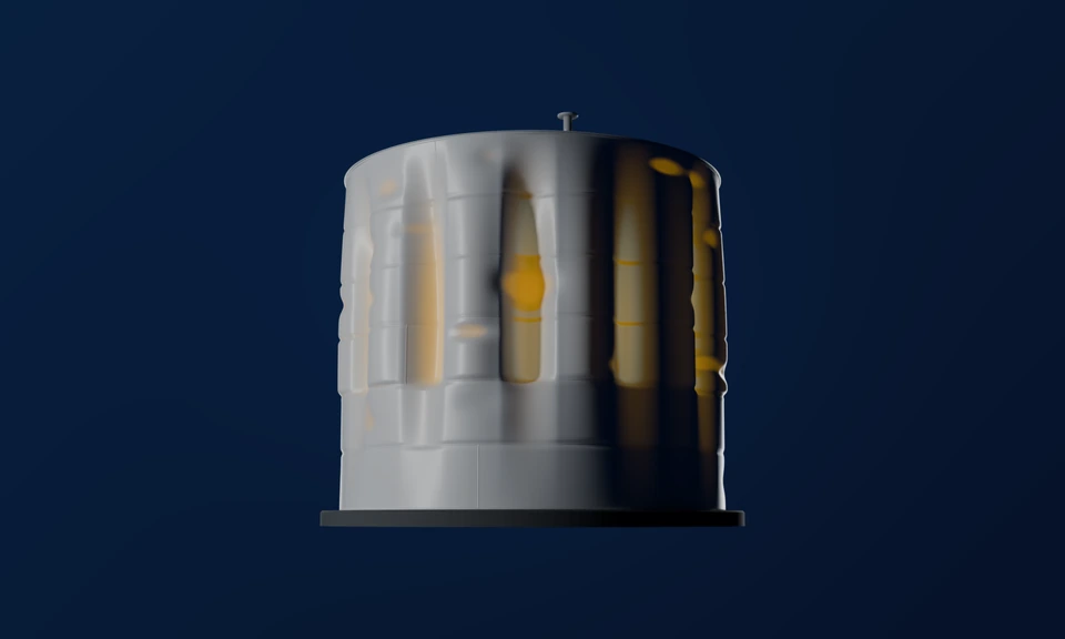
Civil Engineering
Steel silos, storage tanks and containment shells. Self-weight, bulk-solid and vacuum loads, including the EN 1993-1-6:2025 stepped-wall procedure (D.5) for tanks built from courses of different thickness.
Watch the film ↓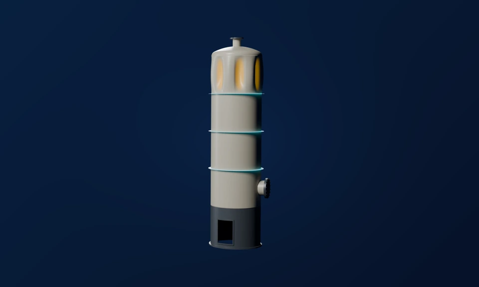
Pressure Vessels
Cylindrical and spherical vessels, torispherical heads and ring-stiffened cylinders under external pressure, with PD 5500 span and ring checks side by side and axial load combined with external pressure.
Watch the film ↓Aerospace
64 seconds, with narration and captions — every statement is also on screen and in the text below.
About this film. An invented aluminium interstage, 3.0 m in diameter with a 2.0 mm wall. On the left, a generic rocket on a schematic flight path shows where the interstage sits and in which order the events happen. The rocket is not a specific vehicle, and the flight path’s curves of speed, air density and dynamic pressure have no scale. The loads of the four flight events are illustrative.
- Max-Q is the moment of maximum dynamic pressure: the rocket is already fast while the air is still dense. In this film it is also the event with the largest bending moment.
- The separation event is a simple stand-in: the small push and bending moment left on the interstage as the first-stage thrust dies away, just before the stages part, treated as steady loads.
- The film assumes the stages part after the thrust has died away, with the interstage staying on the first stage.
- Not modelled: the oscillation after thrust cut-off, which can briefly put the interstage in tension; separation shock; and the loads at the separation joint.
- The imperfection field (radial deviation ×80) and the buckling pattern are schematic; the magnifier draws the wall ×60. The arrows show the wall’s line load. On the gauge they grow from the max-Q load until the Skalnav design value is reached: that margin is the reserve factor.
- The reserve factors use the Skalnav design value for this shell at an assumed imperfection and combine axial load and bending linearly, as Skalnav’s Mission Profile does.
- The reserve factors and the test ratios use Skalnav’s conservative design setting; the app’s default view shows the mean estimate.
- Tests: 87 published laboratory tests on plain metal cylinders, from seven test series, with radius-to-thickness ratios from 256 to 1,040.
- The series: the initial imperfection data bank of Arbocz and co-workers (1979, two series), Kalnins et al. 2015, Jiao et al. 2018, Wang et al. 2019, Krasovsky & Evkin 2021 and Ankalkhope & Jose 2023.
- Each dot is the measured collapse load divided by the Skalnav design value for that test cylinder, at its own geometry and imperfection; none of them is this interstage.
- One test, a cylinder at a radius-to-thickness ratio of 800 (Kalnins et al. 2015), collapsed below the Skalnav design value.
- The tests are axial; the Skalnav design value in bending and the linear N + M interaction are not checked by them.
- The Skalnav design value is fitted to finite-element analyses, not to these tests; the tests are a check.
- App capture: the four events imported from a file in Skalnav’s FE-loads format into the Mission Profile workspace.
- Narration: the voice is synthetic (an open-source text-to-speech model); captions are available in the player.
See also the 79-second Skalnav demo film on the home page.
Wind Energy
58 seconds, with narration and captions — every statement is also on screen and in the text below.
About this film. An invented offshore suction bucket, 15 m in diameter, with an 8.75 m skirt and a 25 mm wall. It is not a real bucket, and the soil values are illustrative.
- The imperfection field (radial deviation ×20) is a synthetic field, not a survey, and its amplitude is illustrative. The buckling patterns are schematic.
- The suction acts on the whole skirt, the buried band included, as Skalnav’s check takes it. The soil is drawn as springs, as the check models it; the film makes no claim about how real buckets buckle in soft ground.
- The gauge shows bedded ÷ classical: the support that Skalnav’s bedded end support credits from the soil stiffness and the embedded length, between no grip (the skirt held by the lid only) and the classical value with the edge pinned at the mudline, never beyond a pin. It is drawn for a round skirt; dents are not included.
- The eleven lobes follow the lobe count the app estimates for this skirt, which is not a buckling prediction; the film keeps that count in every soil.
- Tests: three buckling tests from suction-bucket studies are known to Skalnav, all laboratory models about half a metre across, not real buckets: one model in sand with its tip on a support plate, tested at one depth (Wani & Nallayarasu 2026, Ocean Engineering 343, 123312, doi 10.1016/j.oceaneng.2025.123312), and two steel models without soil (Böhm 2024, Dr.-Ing. dissertation, Leibniz Universität Hannover). The film shows no test result and compares none of them with a Skalnav value; none of them checks the bedded end support, and the test in sand is kept as a reference only.
- App capture: the invented bucket typed into Skalnav’s End Support panel, first in stiff clay, then in very soft clay; the stills show the skirt lengths, the soil stiffness typed in and the regime the panel reports.
- Narration: the voice is synthetic (an open-source text-to-speech model); captions are available in the player.
Civil Engineering
55 seconds, with narration and captions — every statement is also on screen and in the text below.
About this film. A stepped steel tank as tested by Hornung & Saal 2002, the third of their four tanks: 11.5 m in diameter, with courses from 5 mm at the top to 7 mm at the base. The course heights are assumed equal, and the blocked-vent scenario is illustrative.
- The imperfection field (radial deviation ×20) and the buckling pattern are schematic; the elevation strip draws the wall thickness ×250. The dent size is from the published survey: dents reached 33 mm in a 5 mm course.
- The gauge’s KDF 0.45 is measured: the first buckle in Hornung & Saal’s controlled vacuum test, 13.6 mbar, divided by the classical value, 30.5 mbar, the perfect-shell value by EN 1993-1-6:2025 D.5. No Skalnav value is involved.
- The buckle-height chart shows EN 1993-1-6:2025 D.5 perfect-shell values course by course: the critical buckle runs over the full wall height, with an equivalent wall of 5.4 mm.
- Tests: Hornung & Saal 2002, Int. J. Non-Linear Mech. 37:605–621, doi 10.1016/S0020-7462(01)00087-7: four tanks, with the first buckle and the ultimate as published. The EN class C values are computed by Skalnav for the three stepped tanks; the tank with a uniform wall is shown as a test only. First buckles fall on both sides of class C; class C stays below every ultimate.
- App capture: the design case with the tested tank’s courses in Skalnav’s EN 1993-1-6:2025 stepped-wall card, at an illustrative design vacuum of 5 mbar.
- Silo coda: Skalnav’s Silo Mode on the design case Cement Silo at Discharge, 5 m in diameter, before and after a blinded filter adds vacuum at the base; the film shows the reserve factor only.
- Narration: the voice is synthetic (an open-source text-to-speech model); captions are available in the player.
Pressure Vessels
60 seconds, with narration and captions — every statement is also on screen and in the text below.
About this film. An illustrative pressure vessel with generic geometry: 2.0 m diameter, 6.0 m straight shell, 8 mm carbon-steel wall, torispherical heads and three external flat-bar rings, either 60 mm × 8 mm (small) or 100 mm × 12 mm (large). It is not a real vessel.
- The imperfection field (radial deviation ×20), the buckling patterns, the failure points and the pressure test are schematic.
- The first gauge shows PD 5500’s collapse curve for slender cylinders, not a result for this vessel.
- The allowables are drawn to scale from PD 5500 clauses 3.6.2.1 (between rings) and 3.6.2.3 (rings), computed for the illustrative vessel along the app’s own PD 5500 path. The film shows no pressure values.
- Wall comparison. For the top span between the large rings at full vacuum, with the same safety factor of 1.5 on both sides, PD 5500 asks for a 5.9 mm wall. The Skalnav design value, at an assumed imperfection and fitted to finite-element results, needs 5.4 mm. This states what the shell itself carries: a PD 5500 design still needs the PD 5500 wall. At both walls the 100 mm × 12 mm rings pass the PD 5500 ring check (3.6.2.3) and DNV-RP-C202 Sec. 3.5. Walls are the smallest that carry full vacuum, on a 0.1 mm grid.
- Test models: Cho et al. 2018 (doi 10.1016/j.ijnaoe.2017.12.002): 7 models that buckled; 2 that failed otherwise are not counted. MacKay et al. 2010 (doi 10.1016/j.marstruc.2010.06.001): 8 intact models, geometry reconstructed from the paper’s figures. The tiles show PD 5500 clause 3.6.2 applied to each paper’s published data; they are not runs of the app. The glyphs are schematic.
- Codes differ on the small ring. PD 5500 (3.6.2.3) accepts the 60 mm × 8 mm flat bars up to 129.3 kPa, past full vacuum; DNV-RP-C202 (Sec. 3.5: ring area 3.5.1 and ring inertia 3.5.2) rates the same rings inadequate already at full vacuum. The film follows PD 5500. Both are design checks with their own safety margins, not predictions of collapse.
- App capture: the illustrative vessel typed into Skalnav’s PD 5500 card; only the card’s “Governs” row and the ring inputs are shown.
- Narration: the voice is synthetic (an open-source text-to-speech model); captions are available in the player.
Don’t see your industry?
Skalnav covers any thin-walled shell structure. Tell us the load case and we’ll show you the relevant regime.