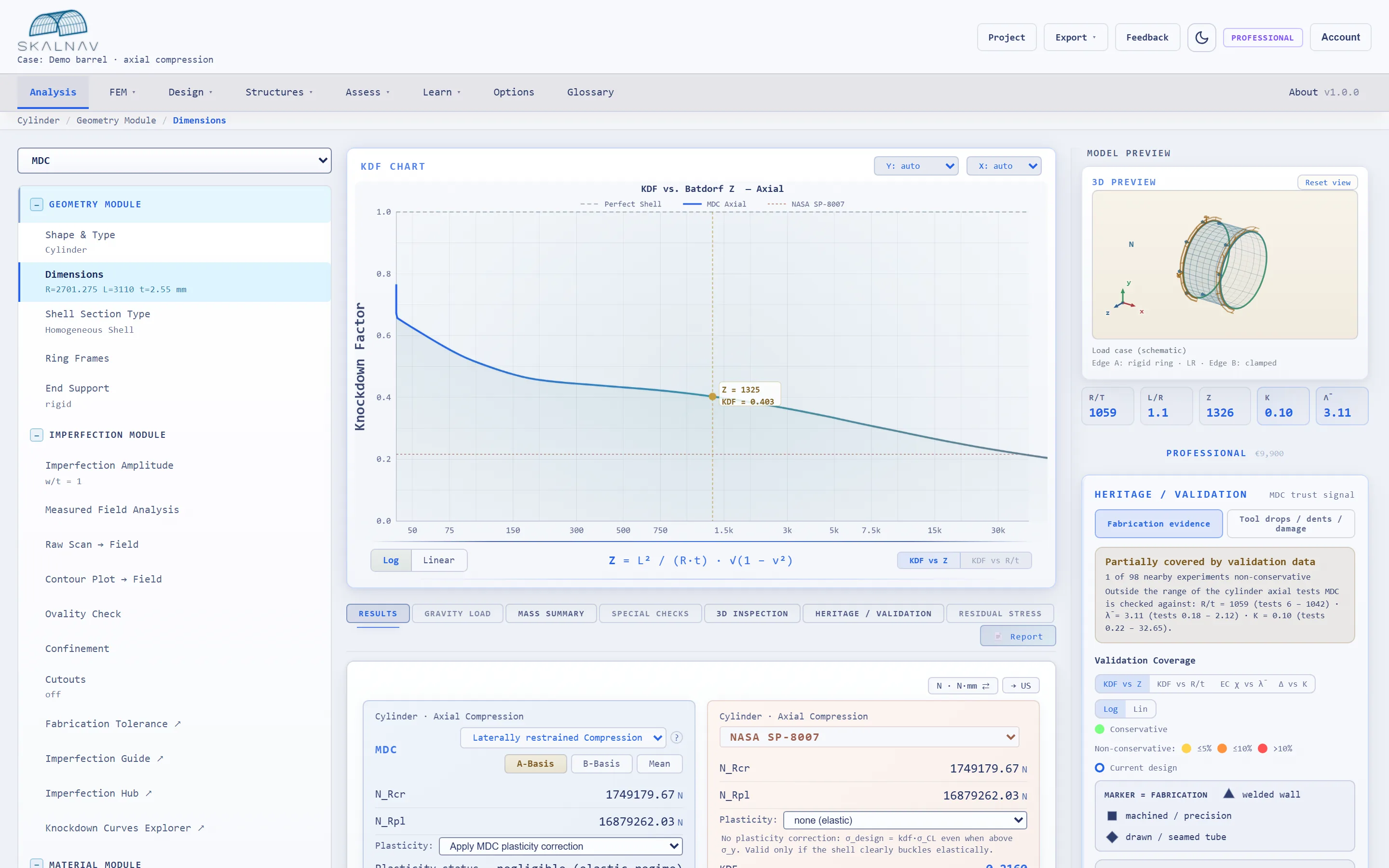
Mechanistic knockdown factors instead of blanket empiricism — validated against 1,000+ collapse experiments, with nine design codes on one workbench.
Peer-reviewed methodology Proc. Royal Society A, 2025No login. Cylinder axial & bending — Skalnav runs in your browser. · Download a sample report (PDF)
Knockdown factors with a mechanical reason behind them: geometry, imperfection sensitivity and buckling regime enter as parameters — not as a one-size-fits-all lower bound from 1968.
The evidence behind every curve: curated collapse experiments from six decades of literature, with documented provenance for every data point — measured values strictly separated from assumed bounds.
The independent cross-check: linear and nonlinear finite element analyses verify the analytical prediction — reproducible and audit-ready.
Collapse tests — physical buckling experiments curated in the Validation Hub (1,000+). Plasticity calibration subset — the 400+ collapse tests, a subset of the 1,000+, used to fit the plasticity correction.
Most structural teams face the same tradeoff: accept conservative empirical factors and carry unnecessary mass, or run expensive nonlinear FE campaigns for every design iteration. Neither approach gives you full visibility into the margin you're working with.
NASA SP-8007 prescribes a single knockdown factor regardless of geometry, imperfection amplitude, or fabrication quality. Every cylinder gets the same penalty. The result is systematic overdesign — kilograms that cost thousands to launch or millions to fabricate.
Running GNIA/GMNIA analyses for every candidate geometry is thorough but slow. Weeks per iteration, high FE expertise required, limited parameter exploration. The design space stays narrow because exploration is costly.
When different standards give different allowables for the same shell, which one is correct? Without a transparent, physics-based reference, teams default to the most conservative answer. The margin exists, but it's invisible.
Skalnav computes knockdown factors as a function of geometry (Batdorf Z) and imperfection amplitude (w/t). The result is a transparent, traceable design basis that works across standards — and recovers the structural margin that empirical methods leave behind.
Enter geometry, load case and material. Cylinder, cone, sphere or torispherical head.
Get the knockdown factor with its mechanistic basis: regime, imperfection sensitivity, Basis A/B — in seconds.
Check your result against nine design codes side by side, from NASA SP-8007 to EN 1993-1-6.
Export a verification report with the full experimental evidence trail behind every number.
Three routes to a buckling proof — and what each one costs you in practice.
| Criterion | MDC | NASA SP-8007 | GMNIA/FEM |
|---|---|---|---|
| Time to result | Seconds | Minutes (hand calculation) | Days to weeks |
| Conservatism & KDF basis | Regime-dependent, mechanistically derived; conservatism quantified per curve (A/B basis selectable) | Single empirical lower-bound envelope from 1968 — safe, but blind to why | Exactly as conservative as the imperfection you assume — the result is an analyst choice |
| Imperfection provenance | Measured imperfection data, documented per curve | Implicit — unknown imperfections of mid-century test articles, baked in forever | Analyst-defined (eigenmode, dimple, scan); must be justified case by case |
| Validation basis | 1,000+ curated experiments, cross-checked against full-scale launcher hardware where records are available | The historical test set it was fitted to — no modern full-scale confirmation | Per project — quality stands and falls with model and analyst |
| Required expertise | Design-engineer level: geometry, load case, material in — verified KDF out | Low — the cost is paid in structural mass instead | Nonlinear-FE specialist; days of modeling, meshing and imperfection studies per configuration |
Empirical knockdown factors compress the physics into a single number. MDC keeps the four effects that actually govern shell stability visible, measurable, and traceable.
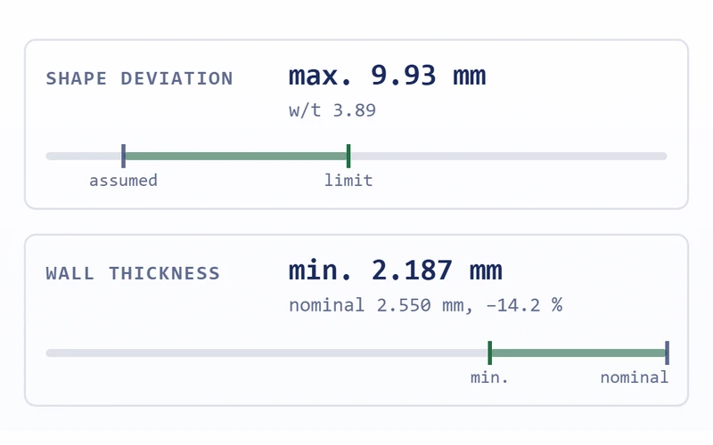
Small geometric deviations (weld distortion, out-of-roundness, dent) drive shells far below their classical buckling limit. MDC sweeps w/t continuously.
Compare amplitudes from Q=A workshop to Q=C field fabrication — see the recoverable margin at each level.
Elastic, transition, plastic — every shell sits in one regime. MDC detects which one governs and surfaces the transition points.
No more accidentally applying an elastic formula to a plastic collapse. The governing regime is stated in every report.
Yielding changes the buckling response — and the interaction with the imperfection hook. MDC applies the physics-based correction, not an empirical knockdown.
Patte d’éléphant correction for combined axial + bending + internal pressure. Calibrated on the plasticity calibration subset — 400+ of the 1,000+ collapse tests.
Orthogrid, stringer-frame, ring-only — stiffening shifts both the global and local buckling modes. MDC verifies every mode, not just the first.
Web buckling, flange crippling, torsional buckling checked at every optimisation candidate. No infeasible optima.
Skalnav handles the structural stability problems that actually appear in real hardware — from rocket tanks to wind turbine towers.
MDC is not a black box. Every knockdown factor can be traced back to mechanistic models and compared against experimental collapse data. The methodology is published, the data is auditable, and the statistical basis is explicit.
Curated buckling test data from 60+ years of published research. Blachut, Seaman, Kaplan-Fung, Wiggins, DNV-GL, and more. Filter by geometry, load case, author, and failure mode. Every MDC curve is overlaid against real collapse measurements — and every record is traceable to its source publication. The underlying MDC calibration programme draws on a curated database of 1,000+ independent, comparison-ready collapse tests — each backed by a deterministically reproducible FEM recomputation, with full per-campaign statistics (see the auto-generated validation report).
The MDC framework is published in the Proceedings of the Royal Society A (2025). Full derivation, full author attribution. The scientific foundation is transparent and independently verifiable — not proprietary curve fitting.
Results are available on A-Basis (p01: 99% survival, 95% confidence), B-Basis (p10: 90% survival), and Mean. Choose the basis that matches your certification requirement and regulatory context.
Skalnav is the engineering surface of more than a decade of research on shell stability. The methodology is peer-reviewed, the underlying data is traceable, and the scope is documented — built as a company, not only a research project.
Structural engineer with 15+ years of shell-buckling research and regulated-industry validation. Doctorate awarded by TU Braunschweig (2018). Lead author of the MDC methodology paper published in Proceedings of the Royal Society A (2025). Based in Braunschweig, Germany.
Shell-buckling expertise and composite-manufacturing know-how. Technical support for product development, and social-media marketing strategy and execution.
Business development, customer outreach, finance/control and operational setup.
Every feature exists because an engineer needed it to close a design trade or defend a result in a design review. Nothing is decorative.
NASA SP-8007, SP-8019, SP-8032, Eurocode 2007 & 2025, DNV RP-C202, ECSS, PD 5500, GOST 34233, and MDC — computed simultaneously on the same geometry and load case. Results side by side. No re-entry, no separate models.
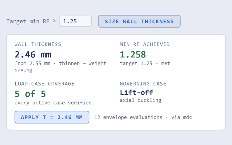
Define a target load. Get the minimum compliant wall thickness across all applicable standards. Integrated with standard sheet thickness catalogues. Answers the question “how thin can I go?” in seconds.
Automated mass minimization for stiffened shells. Orthogrid, stringer-frame, frame-only. Discrete design space search with local stability verification — web buckling, flange crippling, torsional buckling checked at every candidate.
Sweep w/t from 0 to 20 and see exactly how your design responds to manufacturing variability. Identify the threshold where safety margin erodes — before it becomes a test failure or a redesign.
Classical Laminate Theory with full ABD matrix computation. Carbon, aramid, glass presets. Arbitrary stacking sequences. Smeared-thickness conversion for shell buckling. Anisotropy robustness assessment included.
Automatic regime detection across elastic, transition, and plastic domains. Patte d’éléphant correction for combined stress states. 20+ load cases including axial, bending, torsion, external and internal pressure, and all relevant combinations.
1,000+ curated experimental records. Every prediction can be compared against physical test data from published literature. Filter by campaign, geometry, material, failure mode. Discrepancies are visible, not hidden.
PDF, CSV, and JSON export (HTML on the roadmap). Full traceability: inputs, intermediate values, charts, applicable standard, statistical basis, engine version, and design verdict. Structured for inclusion in design review and certification packages — formal review, acceptance, and approval remain with you and your certifying authority.
Each capability is exposed as an interactive workflow — not a checkbox. Click through the tabs to see what the tool does when you open it.
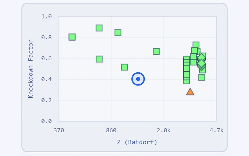
For every MDC analysis, the Hub locates your design point within the 1,000+ curated collapse-test database and flags any nearby experiment that failed below the standards prediction. A non-conservative neighbour is information you cannot get anywhere else — a direct warning to revisit your margins before the design review, not after.
Read the other way, a design surrounded by well-characterised, conservative tests is a documented confidence argument for your review package: the physical record in your parameter neighbourhood, with similarity scores and measured buckling loads.
Whether that evidence supports any given approval remains the decision of the responsible authority — the Hub is supporting evidence, not a substitute for qualification testing. A single query still replaces days of literature search and gives your review package traceable, cited experimental references.
In early design, scan data for your shell does not yet exist — but Eurocode, ECSS, and DNV all require an imperfection amplitude. The Guide closes this gap: a statistically-backed w/t estimate from 172 measured shells covering lab-scale specimens through full-scale aerospace hardware (1970–2024).
Outputs include 90% B-Basis and 95% envelope, split by specimen class, with traceable citations to the original measurement campaigns. Use it to enter a defensible imperfection amplitude before the prototype is built. Provides the imperfection assumptions used in Level 1 analyses, where measured data is not yet available.
The Explorer shows where your shell sits in the regime map and how it moves as parameters change. R/t, L/R, imperfection amplitude, yield stress, and load combination — each slider updates the regime band and the knockdown curve in real time.
Step 1 — Imperfection sensitivity. A perfect shell (w/t = 0) sits in Regime 3 across nearly all geometries — local buckling and material yielding dominate. As imperfection amplitude grows, Regime 1 (imperfection-dominated) and Regime 2 (transition) emerge in the lower-Z range, while higher-Z geometries remain comparatively stable. The slider sweep tells you whether your design crosses into a sensitive regime as imperfections rise — and at what amplitude the crossing happens. This sets a practical threshold for fabrication tolerance.
Step 2 — Plasticity penalty. Plasticity does not affect all regimes equally. Regime 1 shells lose more capacity to yielding than Regime 3 shells. The Explorer makes this asymmetry visible in the same view, so the trade-off between regime and material strength is one decision, not several disconnected analyses.
Why this matters in design. A shell deep in Regime 3 with bounded imperfection amplitude is a Level 0 case — the analytical Skalnav result is sufficient. A shell crossing into Regime 1 or 2 is imperfection-driven; either physical measurement (Level 2) or worst-case envelope assumptions (Level 0) are needed. A shell in an unfavourable regime under any reasonable amplitude is a Level 3 candidate.
If your design lands in an unfavourable regime, the Explorer also shows the geometry levers that would shift it: increasing shell length lowers Z, improving fabrication tolerance lowers w/t — both push toward Regime 3. Ring stiffeners go the opposite direction by raising effective Z (shortening the unsupported field), which can be useful for local mode shaping or manufacturing constraints, but trades regime favourability for those gains. The Explorer quantifies the trade-off rather than guessing at it.
Side-by-side allowable stress for NASA SP-8007, Eurocode 1993-1-6 (2007 and 2025), DNV RP-C202, ECSS-E-HB-32-24A, and MDC-B where each method supports the selected geometry and load case. Governing case is flagged. The delta between the most-conservative and the physics-based answer is the margin you can recover.
Report exports identify the selected method, edition, inputs, and calculated results.
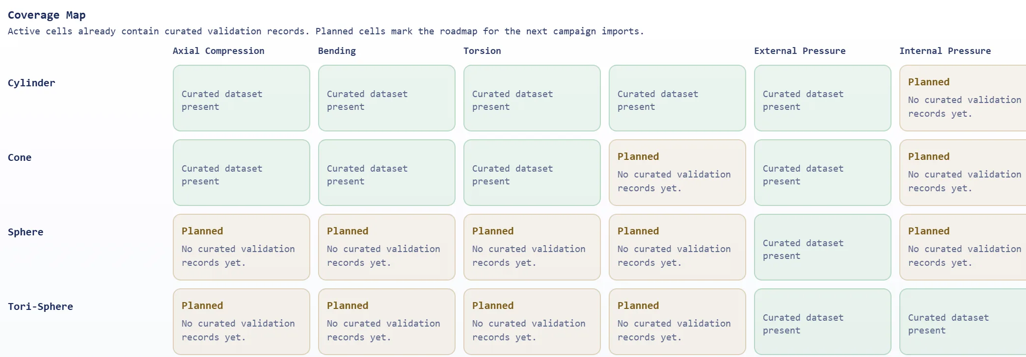
The MDC A-Basis and B-Basis are the statistical design allowables of the Pro tier. We ship only what is validated against our test database. Anything outside the matrix below runs through referenced third-party methods (Eurocode, NASA, DNV, ECSS, GOST) where implemented — free for every registered user.
| Geometry | Axial Compression | Bending | Combined Bending + Compression | External Pressure |
|---|---|---|---|---|
| Cylinder | ✓ MDC A & Bincl. plasticity & internal pressure | ✓ MDC A & Bincl. plasticity & internal pressure | ✓ MDC A & B | β MDC A & B — Betapreview in paid tiers · validation in progress |
| Cone | ✓ MDC A & Bincl. plasticity & internal pressure | ✓ MDC A & Bincl. plasticity & internal pressure | ✓ MDC A & B | β MDC A & B — Betapreview in paid tiers · validation in progress |
| Sphere | — | — | — | ✓ MDC A & Bincl. plasticity |
| Torisphere | — | — | — | ✓ MDC A & Bincl. plasticity |
Load cases marked β Beta are live in the paid tiers as a preview: the MDC engine runs the full calculation, but the statistical validation campaign is still being completed and individual sub-cases carry documented limitations — results are flagged accordingly in the app. Referenced third-party methods (NASA, Eurocode, DNV, ECSS, GOST) are available side by side only for their implemented geometry and load-case scopes. General availability follows with the SC2 release once the peer-reviewed methodology is published.
The MDC framework defines a hierarchy of analysis depth. Each level trades effort for tighter design margin. Level 0 is delivered directly by Skalnav; Levels 1 to 3 are delivered as engineering services for programs requiring numerical analysis under MDC methodology.
Direct MDC computation in the tool. No measurement, no FEM, no project setup. Returns a defensible knockdown factor on B-Basis or A-Basis statistical foundation. The right starting point for sizing trades, RFQ responses, and pre-design exploration.
Numerical analysis (your FE solver of choice) using imperfection amplitudes drawn from the MDC shell-imperfection database. Recovers margin compared to Level 0 by using realistic — rather than worst-case — fabrication assumptions. The right level for preliminary design once geometry is fixed.
Numerical analysis using physically measured imperfection data from the actual shell or a fabrication-equivalent specimen. Recovers further margin by removing statistical conservatism. The right level for verification before qualification testing or for shells already in production.
Numerical analysis combined with geometry modification to push the shell into a more favourable regime — typically increasing length to lower Z, improving fabrication tolerance to lower w/t, or accepting Z-raising stiffeners as a deliberate trade. MDC quantifies the regime shift and its KDF impact, replacing intuition with physics-based optimisation. The right level for mass-critical structures and unfavourable starting geometries.
Illustrative analyses prepared during the Skalnav beta program. Public case studies with named partners will follow general availability.
Four representative structures spanning aerospace, energy, process engineering, and launch-vehicle hardware. Each analysed end-to-end in Skalnav — multi-standard, imperfection-aware, with the recoverable margin quantified explicitly.
CFRP-stiffened conical interstage, compared across methods that support composite and stiffened-shell behaviour. The ECSS Chapter 22 comparison is limited to an isotropic, unstiffened cone and is therefore not used for this CFRP claim. Imperfection sensitivity swept from Q=A to Q=C. Governing standard identified per load case.
Illustrative analysis based on publicly-available Ariane-class launcher reference geometry. Not affiliated with or endorsed by ArianeGroup or ESA.
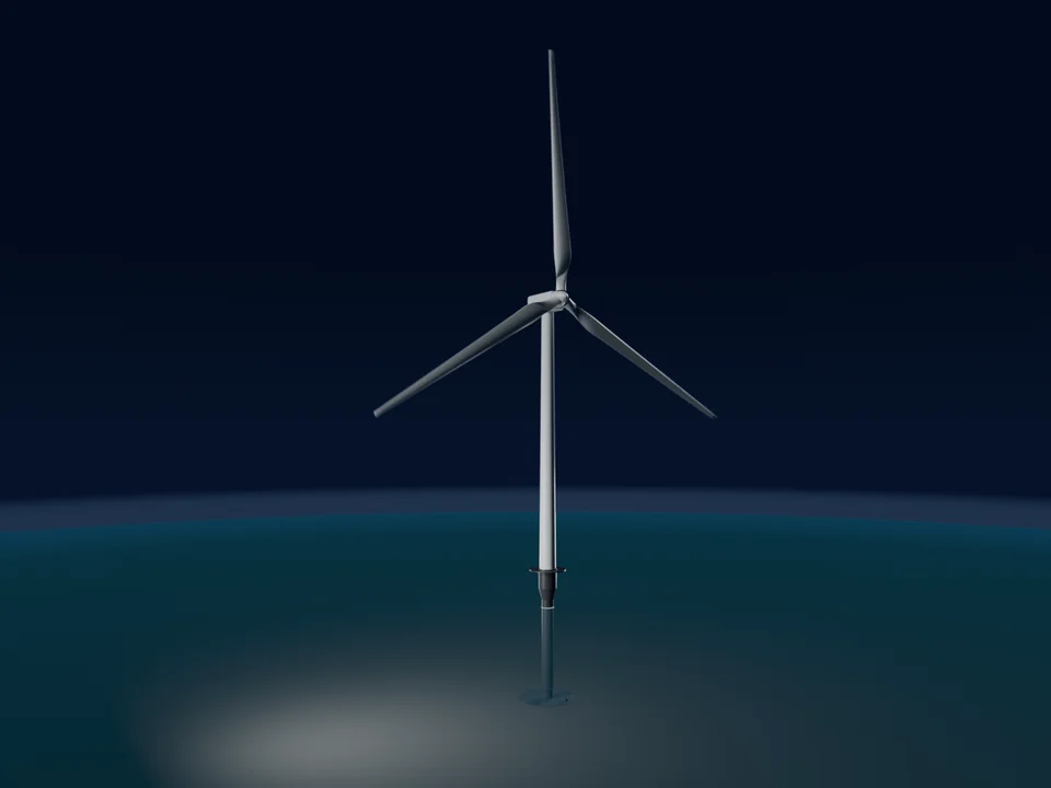
130 m steel monopile, bending-dominated with axial from tower mass. Compared against Eurocode 1993-1-6 (2025), DNV RP-C202, and MDC A-basis. Fatigue excluded — focus on ultimate stability. Ring stiffener spacing optimised.
Illustrative analysis based on generic onshore wind-tower reference geometry. Not affiliated with or endorsed by Vestas, Siemens Gamesa, or any specific OEM.
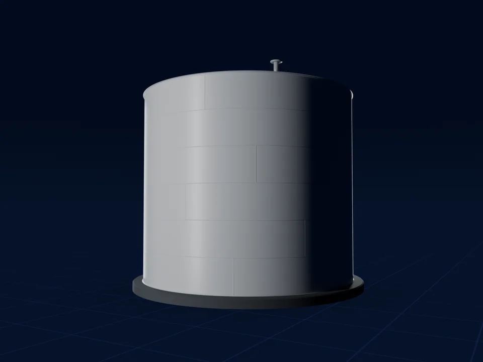
ASME/PD 5500 torisphere for a 12 bar process vessel. Plastic buckling governed — not elastic. Compared against PD 5500, GOST 34233-2, Eurocode, and MDC A-basis. Crown-to-knuckle transition plastic-zone flagged automatically.
Illustrative analysis based on publicly-available process-vessel reference geometry. Not affiliated with or endorsed by any specific OEM.
Ring-plus-stringer CFRP cylinder, local skin buckling and global stability evaluated together. Compared against methods with explicit orthogrid or stiffened-shell support; the isotropic ECSS paths are not presented as an orthogrid check. Stiffener spacing co-optimised with skin thickness.
Illustrative analysis based on publicly-available Vega-class small-launcher reference geometry. Not affiliated with or endorsed by Avio or ESA.
On the reference cases above, the modelled mass saving on a single structure exceeds the annual licence cost by one to two orders of magnitude — an illustration of the leverage, not a guaranteed outcome.
Beta pricing — locked in for early-access subscribers through general availability.
Beta phase: paid subscriptions are not yet available for purchase. Prices shown are preliminary and non-binding — contact us to be notified at commercial launch.
Self-service access to Skalnav — from a no-login first look to organisation-wide licences.
Academic is for research and teaching. Commercial, contract, or client work requires Pro. Validation Hub, Imperfection Hub and the Imperfection Guide are Pro features. Academic accounts are granted automatically for recognised institutional e-mail domains — other addresses start on the registered Explorer tier and can request Academic via Feedback.
You buy the document you hand to your gate — the review-ready proof, not tool access. Delivered by Dr.-Ing. Heinz Wagner. Limited slots per quarter.
| Level | Service | What you receive | Price |
|---|---|---|---|
| 0 | Independent Check | Your geometry/report → independent recalculation in Skalnav, regime classification, imperfection-approach assessment, heritage comparison. A documented second opinion for your review board. | from €4,500 |
| 1 | GMNIA Buckling Verification | Nonlinear FEA per EN 1993-1-6 §9.8 with curated, documented database imperfections. Includes the kGMNIA evidence package (§9.8.4(39) check cases from the test database). | from €18,000 |
| 2 | Measured-Imperfection Allowables | You supply the measurement data (3D / laser scans of your shells — the measurement itself is not part of this service); we evaluate it per EN 1993-1-6 §9.4 and run FEA with your measured imperfections, regime-correct form, Monte Carlo → defensible A-/B-Basis allowable incl. representativeness documentation. | from €30,000 |
| 3 | Review Defense | Geometry optimisation with iterative FEA + methodology presentation and personal representation in your external review (PDR/CDR/QR or Prüfamt). | from €45,000 |
| 4 | Method Qualification Program | Per customer configuration: full V&V dossier, benchmark suite, test correlation, independent replication, review data package, support through QR. | project pricing, from €150,000 |
Every engagement from Level 1 includes Team access for your team for the project duration. 25% of the engagement fee is creditable toward your first annual licence. NDA / DPA on request.
Large aerospace, defence, and energy organisations cannot procure a credit-card subscription — and the Pro tier is not built for their workflow. The Enterprise package exists to meet the concrete, often non-negotiable requirements these organisations bring to any external tool.
Enterprise capabilities are scoped and delivered on a per-customer basis. The list below describes what we build with you — most items are engineered to your environment rather than shipped off the shelf. Concrete timelines, pricing, and reference architectures are part of the scoping conversation.
Features marked “on request” — including SSO (SAML/OIDC), on-premise deployment, uptime SLAs, and additional export formats — are not part of standard subscriptions. They are subject to a separate written agreement and, where applicable, to feasibility, scheduling, and regulatory review. Contact us for current availability.
Your engineers drive MDC directly from Python, MATLAB, or their optimisation pipeline — no browser required. Typical use: sweep 10,000 geometry candidates inside your existing FE or optimisation workflow, pull MDC allowables for each, feed them into your mass-optimiser.
Embed your company’s internal knockdown factors, fabrication-quality classes, or proprietary design handbook alongside referenced third-party methods. Ideal for organisations with decades of in-house test data or bespoke mission-specific reduction factors (e.g. ESA-ECSS plus your internal amendments).
Your staff sign in once with their corporate identity (Azure AD, Okta, Keycloak). No separate MDC passwords, no shadow accounts, instant de-provisioning when an employee leaves. Required by every IT security department above a certain size.
Run MDC entirely inside your firewall — on your own servers, in your own data centre, or in a controlled cloud tenant (AWS GovCloud, OVH SecNumCloud, Bleu, private Azure). Mandatory for ITAR, export-controlled, classified, or IP-sensitive programmes where geometry data must never leave the organisation.
A named engineer (not a ticket queue) is assigned to your account. Direct email & phone contact, scheduled review calls, support for internal tool-qualification exercises (ECSS-E-ST-40, DO-330), and bespoke validation studies against your reference cases.
Contractual availability commitment with the target (e.g. 99.9 %), maintenance windows, incident reporting, and service credits defined in the written agreement — scoped together with the hosting model your programme requires. Enterprise procurement requires this in writing.
Formal quotation with VAT-ID, purchase-order workflow, annual framework agreement, NDA, Auftragsverarbeitungsvertrag (DPA under GDPR Art. 28), supplier-qualification questionnaires, export-control declarations. The things large buyers cannot close a deal without.
Optional pricing model tied to delivered value rather than seats. Example: a programme saves 5 % structural mass on a launcher upper stage → licence fee is a fraction of the demonstrated launch-cost saving. Aligns incentives on both sides.
The Pro tier (€9,900 / user / year, plus VAT) is the right choice for individual structural engineers, small consultancies, and early evaluation inside larger organisations. It covers the full analytical capability, all bases, audit-ready reports, and the complete standards set — licensed for use of results within your own organisation. Delivering reports to your clients as part of your services requires the Team tier.
You need Enterprise as soon as any of the following apply:
→ Talk to us — we’ll scope the right setup, share a reference architecture, and prepare the paperwork your procurement team will ask for.
SP-8007 gives a single empirical lower bound fitted to test data from the 1960s. Skalnav's MDC approach derives knockdown factors mechanistically from geometry, imperfection measures and buckling regime — and shows you the experimental evidence behind each curve. You can display both side by side in every analysis.
Skalnav computes and documents knockdown factors alongside nine established design codes, with full traceability of the underlying evidence. Whether a mechanistic KDF is admissible as the primary basis of a proof depends on your project's verification plan and approval authority — that decision always stays with them. Many teams use Skalnav today to justify margins, quantify the conservatism of code values, and cross-check their primary method against the experimental record.
From six decades of published collapse experiments — 1,000+ curated records in the ValidationHub with documented provenance for every data point, measured values strictly separated from assumed bounds.
Yes — watch the demo, download the sample verification report, or open Skalnav directly in your browser: cylinder axial and bending work without a login.
Skalnav gives structural teams the analytical foundation to design lighter, validate faster, and document every result with full traceability. Start in the free Preview mode — no commitment, no credit card.
Read the Publication — Proc. R. Soc. A, 2025